
Integrating Inverted Roller Screws with Frameless Hollow-Shaft Motors: Direct-Drive Actuator Engineering, Thermal Management, and Procurement Guide
Integrate inverted roller screws with frameless hollow-shaft motors. Compare thermal paths, bearing interfaces and sourcing options, then prepare your OEM RFQ.
Integrating inverted roller screws with frameless hollow-shaft motors can shorten the mechanical drive train by making the rotating nut carry the motor rotor. The useful trade-off is fewer coupling interfaces versus greater responsibility for the shared bearing, air-gap and thermal design. A frameless motor that fits around the nut is only a candidate until its torque-speed envelope, hot clearances and load path have been checked together.
This guide is for mechanical designers and OEM procurement teams comparing a component kit, an integrated cartridge or a complete electric cylinder. It covers a rotating nut and a translating, non-rotating output rod; other screw arrangements need their own analysis. Here, direct drive means no belt, gearbox or coupling between motor rotor and nut; the screw still converts rotary motion into linear travel.
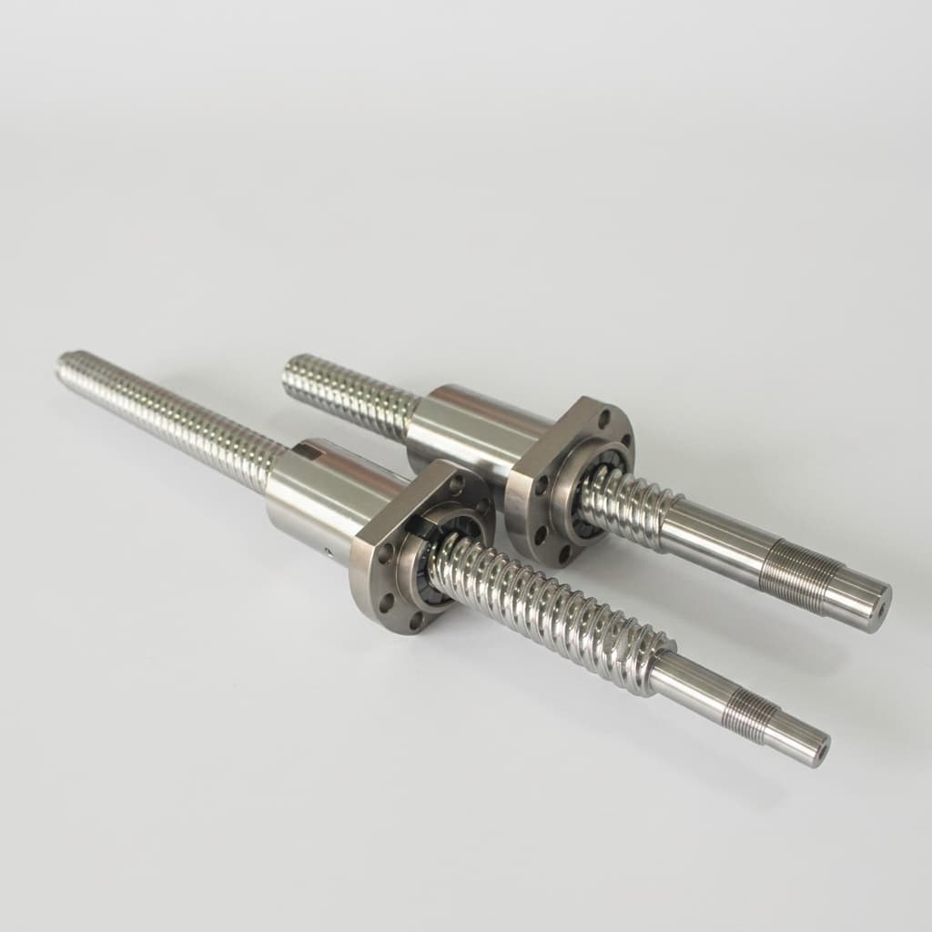
Publication and technical review: October 26, 2026. Scope: global OEM engineering and sourcing, in SI units. The calculations below are illustrative screening estimates, not measured product performance, supplier capability certification or an aerospace/medical qualification. Final limits depend on the selected screw, motor, bearings, lubricant, housing and duty cycle. The header image shows roller screw components for context, not a completed motor-integrated assembly.
Preparing a design review? Send an actuator integration RFQ with stroke, thrust versus time, speed, bus voltage and available envelope. Mark unknown inputs as TBD so the missing decisions remain visible.
Direct-Drive Coaxial Architecture: Cross-Sectional Anatomy
The housing supports the stator and bearing seats. A retained rotor sleeve connects to the elongated inverted nut, while an anti-rotation feature lets the output rod translate. This architecture has a commercial precedent: the Exlar GTX installation manual, section 1.1 describes a roller screw integrated into a brushless servomotor rotor. That example does not establish compatibility between arbitrary screw and motor kits.
Kinematic Comparison: Why Inverted Geometry Enables Direct Drive
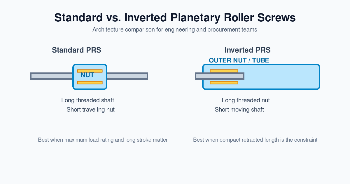
A common standard planetary roller screw arrangement uses a rotating long screw and a translating short nut. Other rotating-nut arrangements are possible, so inverted geometry is not the only way to build a coaxial actuator.
In the inverted arrangement discussed here:
- The nut is the long threaded member. Its functional internal thread accommodates the stroke and roller engagement, plus the required end allowances.
- The output rod has a localized threaded section. The remaining rod geometry provides extension, guidance and sealing interfaces.
- The rollers transmit load between rod and nut. Roller count, synchronization and retention details depend on the supplier design.
Why This Geometrical Inversion Matters for Actuators
- Mechanical nesting: a cylindrical nut can carry a separate motor rotor sleeve. Directly bonding magnets to the nut is a design option, not a prerequisite; assembly and repair access matter.
- Envelope: overlapping motor and screw lengths can reduce the package compared with a motor mounted behind a screw. Do not add stroke to a nut length that already contains the stroke allowance; compare actual retracted CAD envelopes including bearings, brake, encoder, seals and connectors.
- Dynamics: removing a coupling removes one compliance source. Rotor inertia, rod and housing stiffness, payload and control tuning still determine bandwidth. Neither zero backlash nor a specific resonance frequency follows from the architecture alone.
Critical Engineering Interfaces & Sizing Tolerances
Use a joint screw/motor/bearing interface drawing rather than importing generic fit or runout numbers. Moog's frameless motor page identifies rotor-stator sets for integration into an existing mechanical assembly; it does not approve a particular hollow bore or thermal interface for this actuator.
The following seven-row matrix is an RFQ acceptance framework. Each numerical limit remains TBD until the suppliers agree the datum system, temperature and inspection method.
| Interface | Engineering decision to close | Failure mode to evaluate | Evidence to request |
|---|---|---|---|
| Nut OD to rotor carrier | Fit, bond line or mechanical retention; datum and hot clearance | Rotor slip, nut distortion or fretting | Dimensioned interface drawing and retention validation |
| Stator ID to rotor sleeve | Nominal and minimum running air gap over temperature and speed | Eccentric magnetic force or rotor rub | Worst-case radial stack with measured assembled runout |
| Nut journal to thrust bearing | Ring fit, shoulder geometry and axial retention | Ring creep, misalignment or preload change | Bearing supplier fit recommendation and assembly record |
| Bearing outer ring to housing | Bore geometry, support stiffness and thermal growth path | Distorted rings or overconstraint | Bore inspection and cold/hot preload assessment |
| Output rod to guide and seal | Alignment, straightness, seal compatibility and guide capacity | Seal wear or unwanted side load on screw | Full-stroke alignment check and seal specification |
| Anti-rotation guide | Reaction torque, clearance, stiffness and contamination protection | Rod rotation, lost motion or binding | Torque load case and reversal test |
| Roller synchronization parts | Supplier-controlled geometry and assembly procedure | Skewing, timing loss or local overload | Supplier inspection plan and traceable assembly acceptance |
Reproducible Screening Example: Thrust, Speed and Heat
Assumptions, not test results: axial thrust F = 10,000 N; lead p = 0.005 m/rev; speed v = 0.10 m/s; assumed screw efficiency η = 0.85 at this operating point. Ignore acceleration and external drag for this first estimate.
- Nut speed:
n = 60v / p = 1,200 rpm. - Screw input torque:
T = Fp / (2πη) = 9.36 N·m. - Useful linear power:
Pout = Fv = 1,000 W. - Screw input power:
Pin = Pout / η = 1,176 W; estimated screw conversion loss is about176 W.
These are three requirements to check simultaneously, not independent catalog maxima. Add acceleration torque from total reflected inertia, measured seal/bearing drag and a justified design margin. For a repeating cycle, compute RMS motor torque from each segment's torque and duration, then check the installed motor's continuous rating and peak torque duration at the required speed and bus voltage. At a loaded dwell, output power is zero but holding current can still generate heat.
For an additional illustrative motor-loss estimate, balanced sinusoidal phase current of 5 A RMS and hot phase resistance of 0.4 Ω give Pcu = 3 × Iphase,rms² × Rphase = 30 W. Do not substitute line-to-line resistance or peak/q-axis current without converting its convention. Combined screw and copper loss at this point is about 206 W, before iron, bearing and seal losses. This arithmetic supplies a heat-budget input; it does not predict winding or grease temperature, cooling flow, actuator life or a quoted supplier rating.
Managing the Thermal Loop: Motor I²R Losses vs. Screw Lubrication
Thermal coupling is a design constraint because motor, nut, bearings and housing share a compact envelope. The motor windings, magnetic circuit, screw contacts, seals and bearings generate heat through different mechanisms. Model both the radial path from stator to housing and the paths through the air gap, rotor, nut and bearings; their relative contributions depend on the assembly.
Windings / stator ── mounting interface ── housing ── ambient or coolant
       │                                     │
       └── air-gap heat transfer ── rotor / nut ── bearing supports
                                       │
                              rollers / lubricant / output rod
This is a conceptual heat-flow map, not a temperature prediction. A cool housing does not establish a safe winding or internal lubricant temperature.
Consequences of Unmitigated Heat Transfer
- Lubrication: oil viscosity and grease life change with temperature, speed, loading and contamination. Use the approved lubricant and maintenance interval. The Exlar GTX manual, section 6.1 explicitly treats temperature, speed and load as lubrication factors; its renewal guidance is product-specific.
- Differential expansion: a first estimate is
ΔL = αLΔT. For an illustrative 200 mm steel member, assumed α = 12 × 10⁻⁶/K and a 30 K rise give 0.072 mm free growth. Actual relative movement also depends on the housing, supports and temperature gradients. Check whether growth changes screw preload, bearing preload or encoder reference. - Rotor materials: magnet coercivity, operating load line, adhesive and sleeve limits must be checked at the predicted rotor temperature. A magnet grade name or winding insulation class alone does not establish an assembly temperature limit.
Engineering Thermal Mitigation Strategies
- Define the heat sink first. Specify ambient or coolant conditions, housing contact area and thermal resistance at the stator interface. Select natural, forced-air or liquid cooling from the loss model and installed tests, not a universal duty-cycle threshold.
- Evaluate sleeve trade-offs. A sleeve changes air gap, mechanical retention, thermal conduction and potentially eddy-current loss. Do not prescribe a material or thickness without checking those effects together.
- Approve lubricant compatibility. Specify grease type, quantity, speed/load/temperature limits, seal compatibility and renewal procedure. A high dropping point is not a continuous operating rating; do not mix greases without approval.
- Measure the installed duty cycle. Monitor winding and bearing-adjacent temperatures and validate any model estimate of inaccessible nut/rotor temperature. Agree warning, derating and shutdown thresholds with both suppliers.
Thrust Bearing Topologies and Load Path Isolation
Draw the structural path explicitly: output rod → roller contacts → inverted nut and its structural shoulder/carrier → thrust bearings → housing → machine mount. The nut may also be the motor rotor carrier, so it is incorrect to say that thrust always bypasses every rotor-associated part. The design objective is to keep the magnet bond and stator outside the primary thrust-retention path.
A frameless rotor-stator set supplies torque; the integrator must specify its support bearings and structural load capacity. Select the bearing arrangement for bidirectional load, speed, required stiffness, installation fits and thermal conditions.
Bearing Arrangement Trade-Offs
1. Back-to-Back Preloaded Angular Contact Support
A suitable matched pair or double-row screw-support bearing can react reversing axial loads and provide tilting stiffness. Contact angle, speed limit, preload and life are model-specific. Assess ring fits and housing distortion rather than assuming a generic stiffness value.
2. Fixed-Floating Dual Arrangement
One support locates the nut axially; another provides radial support while permitting intended axial thermal movement. The floating function must be real in the bearing or fit arrangement and retain adequate radial alignment. This does not eliminate local temperature-driven preload changes inside the locating bearing itself.
3. Heavy-Duty Thrust Support
For press-duty loads, specialist thrust arrangements may be candidates. Check bidirectional support, minimum load, speed, lubrication and radial guidance with the bearing supplier. A spherical roller thrust bearing alone does not replace a complete reversing-load support system.
Concentricity, Runout, and Unbalanced Magnetic Pull
An eccentric rotor produces an uneven air gap and can increase magnetic loading, vibration and rub risk. Specify the rotor-seat datum relative to the bearing axis and inspect the complete nut/rotor assembly, including retention sleeve and magnet placement.
Prepare a worst-case clearance budget for dimensional tolerances, assembled eccentricity, bearing motion, thermal growth and load/speed deflection. Distinguish TIR from radial eccentricity; they are not interchangeable measurements. Set balancing requirements from assembled mass distribution, operating speed and the agreed test procedure. There is no universal runout value or balancing grade that approves every nut/motor combination.
Sourcing & Procurement Framework: Make vs. Buy Decision Spectrum
Compare total delivered cost and who owns each acceptance test. A lower component quotation can be outweighed by integration fixtures, rejected assemblies and repeated thermal validation.
Component kit        → OEM owns integration, tooling and acceptance
Modular core         → Supplier integrates agreed screw/rotor/bearing interfaces
Complete cylinder    → Supplier delivers an actuator within a defined envelope
Sourcing Model Comparison Matrix
| Evaluation Dimension | Level 1: Component-Level Sourcing | Level 2: Modular Actuator Core | Level 3: Turnkey Electric Cylinder |
|---|---|---|---|
| Purchased scope | Screw, frameless motor, bearings and seals bought separately | Agreed nut/rotor/bearing subassembly with interface drawings | Packaged actuator with specified feedback and connectors |
| OEM assembly | Retention, precision assembly, cleanliness and balancing processes | Housing installation, cooling interface and system wiring | Mechanical mounting, drive integration and commissioning |
| Tolerance ownership | OEM coordinates component tolerances | Supplier owns contracted core datums; OEM owns housing interfaces | Vendor owns internal datums; OEM owns mounting alignment |
| Warranty boundary | Agree cross-vendor failure investigation before ordering | Define coverage for rotor retention, bearings and screw explicitly | Confirm installation exclusions and system-level responsibilities |
| Packaging flexibility | High, subject to component and process constraints | Custom housing possible within agreed core interfaces | Limited by catalog or negotiated custom envelope |
| Cost comparison | Include tooling, metrology, labor, yield and rework | Include integration charge and incoming acceptance | Include drive, cables, mounting and commissioning |
| Suitable buying condition | OEM has precision assembly capability and sufficient volume | Supplier can prove the integrated interfaces and OEM needs custom packaging | Schedule and validated package matter more than envelope freedom |
A modular core is a useful option when a supplier can document rotor retention, assembled runout and bearing preload, and the OEM can validate its housing and cooling. It is not automatically cheaper or lower risk. Ask all bidders for prototype cost, tooling/NRE ownership, sample and production lead times, quantity breaks, delivery terms, destination, traceability and change-notification obligations.
Use the interface matrix above in a joint engineering and procurement review before freezing a purchase specification. Request evidence against the proposed assembly drawing rather than a general promise of micron-level capability.
Technical Audit & RFQ Checklist for Direct-Drive Actuators
A. Kinematics & Dynamic Sizing
- Specify thrust, speed, acceleration, dwell and cycle count for every motion segment, including peak duration.
- Obtain the screw supplier's load-life calculation method, rated-life basis, lubrication assumptions and preload treatment.
- Verify rotating-nut speed limits, support dynamics and rod buckling at the worst extension and mounting condition.
- Check motor torque-speed capability, RMS heating, bus voltage, drive current conventions and regeneration during deceleration.
B. Motor & Thermal Interfaces
- Agree ambient/coolant conditions and the installed stator-to-housing thermal interface.
- Confirm motor winding, magnet, adhesive, sleeve, bearing, grease and seal temperature limits separately.
- Approve rotor retention for speed, torque, thermal cycling and assembly process.
- Define temperature sensors, derating thresholds and a duty-cycle thermal acceptance test.
C. Mechanical Precision & Bearing Assembly
- Freeze datums, fits, hot clearances and assembled runout limits jointly with the motor and bearing suppliers.
- Document the axial thrust path, locating/floating functions and cold/hot bearing preload.
- Provide guidance for radial/moment loads and define output-rod anti-rotation and seal arrangements.
- Specify allowable reversal lost motion and loaded stiffness at operating temperature, rather than the label “zero backlash” alone.
D. Quality Verification & Procurement Acceptance
- Request traceable lead/travel-error measurements over the agreed stroke and temperature, plus an explicit acceptance method. ISO 3408-3 concerns ball screws; any use of its test definitions for a roller screw must be agreed in writing and does not establish roller-screw certification.
- Agree assembled rotor runout/balance inspection, no-load friction torque and full-stroke functional tests.
- Require loaded reversal and representative duty-cycle thermal tests with recorded setup, limits and pass/fail criteria.
- Close brake/holding requirements, delivery terms, documentation, NRE ownership, warranty boundaries and supplier change control before the PO.
Frequently Asked Questions (FAQ)
Can a standard planetary roller screw also work with a hollow motor?
Yes, depending on whether the screw or nut rotates and how the translating member is guided. Compare actual CAD envelopes, rotating inertia, support layout and service access. Inverted geometry is attractive when a long rotating nut can carry the rotor while the rod extends, but it is not universally superior.
What can cause premature bearing failure in a direct-drive actuator?
Investigate preload and fits, thermal growth, lubrication, contamination, alignment and external loads. Do not rank these causes or assign a preload multiplier without failure-analysis data. Include cold and hot friction-torque measurements and the actual load history in the supplier investigation.
How much radial side load can the extending push rod support?
Do not assume a permissible percentage of axial capacity. Guide external radial and moment loads independently unless the complete actuator supplier publishes a suitable rod/bushing rating. Exlar's GTX manual, section 3.2.1, warns that side loading and misalignment shorten life; that warning is not a quantitative side-load rating for another actuator.
Can an inverted roller screw actuator backdrive under power loss?
It can. Do not assume self-locking or rely on energized motor holding torque after power loss. Evaluate load holding, stopping energy and failure behavior for the application. The GTX manual, section 2.2.5, describes an optional holding brake; a holding brake must not be assumed to provide dynamic emergency stopping or a complete safety function.
Should we specify zero-backlash preload or small axial clearance?
Specify acceptable reversal lost motion and stiffness under the actual load and temperature range, then compare preload options with the screw supplier. Higher preload can increase drag and heat, while clearance can degrade positioning. There is no general speed threshold that makes one option correct, and motor encoder resolution alone does not establish output-rod accuracy.
Is an integrated electric actuator lighter or more efficient than hydraulics?
Compare the same duty cycle and system boundary: cylinder/actuator, motor or pump, drive, reservoir, hoses, cooling, holding and regeneration. Shared hydraulic power units and long static dwells can change the result. No fixed weight or energy-saving percentage follows from choosing an inverted roller screw.
Next Steps: Engineering Collaboration & Custom Sourcing
Request an actuator integration review with the envelope drawing, stroke, load/speed timeline, bus voltage, ambient/cooling conditions, target quantity and delivery country. Ask which party will supply and warrant the screw, rotor retention, bearings and housing interfaces, and request a written feasibility response identifying unverified items. A quotation or component drawing is not approval of the assembled actuator's thermal performance or life.
Sources & Credible References
Sources checked October 26, 2026. Manufacturer guidance below applies to its named products; the interface matrix, procurement framework and hypothetical calculations are this guide's engineering synthesis, not supplier test results or endorsements.
- Curtiss-Wright / Exlar — GTX Series Installation & Service Instructions, Rev. J, PN75557, December 19, 2023: section 1.1 for integrated screw/motor architecture; sections 2.2.5–2.2.6 and 3.2.1 for holding, anti-rotation and alignment; section 6.1 for product-specific lubrication factors. These instructions do not rate a custom actuator assembled from unrelated parts.
- Moog — Silencer Series Brushless DC Frameless Motors: supports rotor-stator part-set integration as a sourcing option. Bore, retention, thermal conditions and compatibility require the selected model's drawing and supplier confirmation.
- ISO 3408-3:2006 — Ball screws, Part 3: Acceptance conditions and acceptance tests: identifies the ball-screw acceptance-test scope. The public record is not the full standard, a roller-screw load-life method or proof of conformity for this design.
Author

Categories
More Posts
Inverted vs. Standard Planetary Roller Screws: Engineering & Procurement Guide
A comprehensive decision framework comparing standard and inverted planetary roller screws. Learn the engineering trade-offs in load capacity, packaging, cost, and lubrication.
Custom vs. Standard Inverted Roller Screws: Lead Time, Cost Analysis, and RFQ Best Practices
A comprehensive procurement and engineering guide to choosing between standard and custom inverted roller screws, covering lead times, TCO, and RFQ checklists.
Inverted Roller Screw Supplier Selection: 5 Quality Control Metrics Procurement Must Check
A comprehensive supplier audit checklist for procurement teams and engineers evaluating inverted roller screw manufacturers, covering ISO standards and metrology.